The ship has currently 721 HP(530kW), but can be easily upgraded to +- 958 HP(662 kW) , at cost of max. 75.000 US$ (or can be done by any local SKL-dealer).
Extremely suitable for conversion into a transatlantic yacht, an offer for this conversion to seaworthy world cruising (ice-class!) is obtainable.
(Than est. +- 14 BP) Also additional "AQUAMASTER" (Steerable BOW THRUSTER) given than a total of 19 T BP can be installed at cost.(All above is NOT required for Naval or yacht-conversion use)
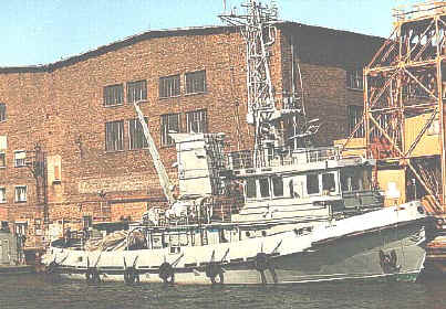
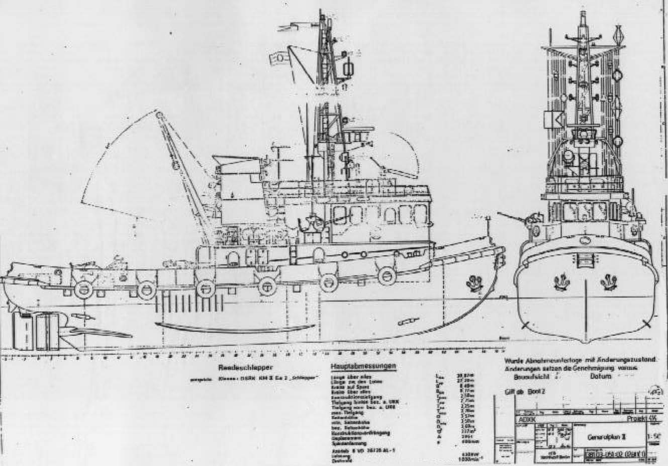
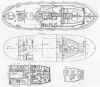
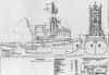
N.B.C. -TUGBOAT TYPE '414'
Nuclear, Biological and Chemical protected MULTI PURPOSE tugboat.
(Towing, fire fighting, salvage, evacuation, diving and general assistance in
hazardous area's.) Build to DSRK, highest naval specifications +under
Germanischer Lloyd-class 100 A5KE2 TUG,MC E AUT.
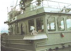
1. TYPE Tug boat to handle ships and swimming objects at sea, in ports and at roadsteads with continued upper deck and in the upper deck 'swing-flexible' hanged deck-house, including the living accommodations.
2. PURPOSE
2.1 Primary tasks. Handle ships and swimming objects at sea, in seaports and at roadstead's, or tow ships over short and medium distances.
2.2 Secondary tasks.Fire fighting (Water- gas and foam fire fighting systems).
Ice breaking of up to 60 cm firm ice thickness.
Salvage/recovery operations.
Diving operations.
3. TECHNICAL SPECIFICATIONS
3.1 Main specifications.
Length over all 30,87 m
Width over all 8,77 m
Middle depth 2,50m
Height 3,69 m
Standard displacement= 286 Ton
Gross Tonnage (GL) = 262 Ton
Net Tonnage (GL) = 62 Ton
Speed = 11 Knots (x 1,852 = 20,372 km/Hr.)
Bollard pull(min design requirement) = 100 Kilo Newton (With unmodified engine)effective:
10,9 T B with AL-1 / 14 T with 1 AL-2 /
19 T B with AL-2 + "AQUAMASTER"
3.2. Safety-technical clarification.
3.2.1 Classification. The ship is build according to the DSRK regulations + highest naval specifications and brought under GERMANISCHER LLOYD class, (100A5KE 2 TUG , MC E AUT).
3.2.2 Operation area. 'BALTIC SEA'
Seaworthness : Wind force 7 Beaufort, Sea state 6 without container.
Wind force 5 Beaufort, Sea state 4 with container.
Ice condition : Up to 60 cm firm ice layer.
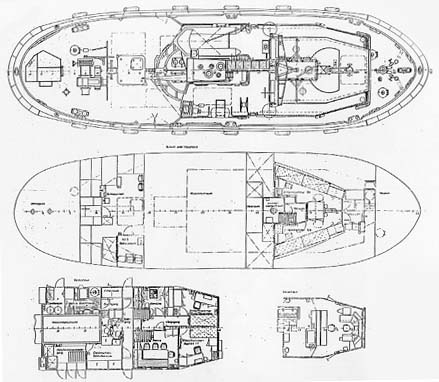
4. SHIPBUILDING DESCRIPTION
The hull is divided by 4 watertight bulkheads into 5 watertight compartments.
The construction is executed in transverse frame building.The shape of the after body guarantees the best water-supply towards the propeller.To protect helm and propeller at backwards sailing, an ice spur is situated at the stern post.
The ship has bilge keels to decrease roll movements.
Plates and profiles are of high graded shipbuilding steel, the signal mast is made of quality aluminium.
The dismountable parts are screw-connected.
These are mainly the signal mast, the complete fitted-out wheel house, the chimney and further subordinated construction elements.
The ship is foreseen of a crane with an 8 meters long cargo boom of 20 kNT (2 Ton), which is fully hydraulic (veer out-in, swing movement).
The calculation of strength, the intact- and leak stability is done according above classification.
The ship's construction allows installation of up to 1.102 Kw (1500 HP) engine.
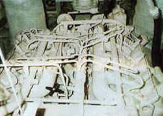
5. ENGINE INSTALLATION
The engine installation is located in the engine room at frame 17 - 38.
The engine room is accessible from the upper deck.
5.1 Main engine. The ship is foreseen of a single shaft installation, existing of :
- S.K.L. Magdeburg Diesel engine 6 VD-26/20 AL-1 (Simple modification to AL-2 possible).
- Flexible clutch KJZ 2/130 W.
- Gearbox SWG K 400
- Intermediate shaft
- Controllable (c/p) propeller system Hy 220
- Propeller shaft
- Propeller NV 46 / 4-A.
- Electrical remote control
The Diesel engine 6 VD-26/20 AL-1 is a 6-cylinder 4-stroke line engine, with exhaust-gas turbo charge and turbo air cooling.
The engine has 530 kW (721 HP) at 1.000 RPM. (Or 705 kW / 958 HP with AL-2 mod).
The cooling is by fresh water with a corrosion protection additive.
The engine is started by compressed air and is foreseen of an electric regulating device for the RPM (rotations per minute).
The gearbox is a 2-step straight toothed gear with shift-clutch and build-in thrust bearing.
The engine is surveillanced by a control-warning system.
Remote control is by one-handle, with combination possibilities for the Diesel engine and the controllable propeller.
5.2 Auxiliary engines. For the electrical power supply two elastic supported Diesel generator sets are used:
Diesel engine 6 VD 15,5 / 12 - 2 SRW
Three-phase generator S 22 3 L 4, 75 kVA , 390 V
The engines are electrical started, they are supervised from the central wheel-house.
They are foreseen of a sea-cooled water pump with internal cooling-water heat exchanger.
The parallel use of both generator sets is possible.
5.3 Electrical power supply.
For the voltage fields 380/220 V 50 Hz, there are 2 Diesel generator sets of 75 kVA available.These generators can be used in single or parallel use, at choice of the operator.Starting of the generators is done from the electrical control room, the wheel-house or the engine room.The power supply of the 24-Volt system is in buffer use with the batteries sets, through two rectifiers.The 380-Volt three-phase board net is a four-wire system with isolated mounted star delta cable and ground cable.
The batteries sets have following capacities:
1 Set ship's batteries 360 Ah
1 Set starter batteries 180 Ah
1 Set emergency lights batteries 360 Ah
1 Set emergency radio batteries 180 Ah
The ship has a 63 Ah land-connection and is able to transfer current through a plug system.
5.4 Ship systems and installations.
All pumps and compressors are elastically mounted.
The tube connections are flexible.
On the upper-deck there are transfer- and take over connections for bunker, engine oil, used oil, compressed air, sea water, fresh water and drinking water.
- Fire extinguishing installations. The fire extinguishing installations are for three main tasks foreseen :
- Fire fighting on the ship.
9 hand-held fire extinguishers for beginning fire.
Intervention-water fire extinguishing system 25 m;/h, 0,4 MPa ( = 4,132 kg/cm5)
with 6 connections size C, (5 x water, 1 x foam).
Gas fire extinguishing installation for the engine room and towing part.
In all ship's holds, (except front peak and hind part) there is an ionization fire alarm installed.
- Object fire fighting.
2 mobile extinguishing systems with hoses and a hand-sprayer in the towing part.
Water-foam fire extinguishing system with fire extinguishing- and foam forming pump.
(Foam forming storage 1,5 M;).
- Water protection system.
Filling through fire extinguish pump, sprayers for the decks, irrigation tubes for the ships walls.
- Bilge pump sytem. To bilge the ship's compartments, following pumps are foreseen:
- Bilge pump KR Z1V-50/16/-02 25m;/h, 0,32 MPa ( 3,3056 kg/cm5) 2900 U/min,
with 3-phase motor KMR 100 L2 5,5 kW with autonomous suction step.
- Water jet bilge pump Size 6, 16 m;/Hr.
- Fire extinguish pump (Motor pump) 250 m;/Hr. 0,9 MPa.( 9,297 kg/cm5)
- Transportable salvage pump, 60 m;/h, 0,1 MPa (1,033 kg/cm5), as emergency bilge pump for the engine room.
- Bilge water (-oil) separator BWAE 0,2 , 0,2 m;/Hr.:15 mg/dm;.
The bilgewater piping's are divided in two separate systems:
- Main bilge pipe.
- Bilges with the water-oil separator.
For the use of the water-jet pump, the water is prepared by the assistant fire extinguish pump .The bilging of the with oil contaminated bilge waters, ( towing part, engine room, heating room,steering gear compartment) is done under normal conditions with the bilge water separator.
- Gas fire extinguish system.The gas fire extinguish system is used for fire fighting on the ship.Following rooms are than gassed:
- engine room. - heating room. - towing part.
The application allowance is given from the wheel-house after the corresponding signals are given, the introduction of the fire extinguishing gas is done by a push-button in the wheel-house.After finishing the fire fighting, the gas is to be soaked up by a 24-V mobile ventilator.
- Foam forming system. The foam forming system has the task to add foam to the fire extinguish-water.To prevail constant pressure, there is a dual-seat valve, confirmed with a pneumatic pressure regulator, built in.
The system allows following different uses:
- Pumping of the foam formers in the tank.
- Transfer of the foam formers 1 x D, 1 x C.
- Take over of the foam formers 1 x C.
- Mixing of the foam formers with extinguish water for the water cannon and the tube connections.
- Rinsing the pipe lines with sea- or fresh water after the use of foam.
- Water fire extinguishing system.
The water fire extinguishing system as central fire extinguishing system is divided into :
- Secondary water fire extinguishing system :The secondary water fire extinguishing system serves as fire fighting on the ship.The secondary fire extinguish pump, a liquid-air helical pump KRZ 1 HJ-50/190-09; 25 m;/Hr.;0,4 MPa ( 4,132 kg/cm5), collects in a dispersion pipe with following connections:
-1 x Connection tube from main fire extinguishing system.
-5 x C- connections for water with 20-meter hose and a multi purpose jet-tube for fire fighting at the ship.
-1 x Water hose for the water-jet bilge pump.
-1 x Cooling water hose for the emergency cooling of the main engine and the diesel generators.~
-1 x Rinse water tube for the faeces- and contaminated water cell.
-1 x Fill connection for the salvage suction hose.
-1 x C-connection for the autonomous foam fire extinguishing installation in the engine room.
- Main water fire fighting system.The system is mainly for object fire fighting (other ships, barges, port installations etc., specially in Nuclear, Biological or Chemical hazardous area's.), but it can also be used for fire fighting at the ship.
The fire extinguisher pump, a motor pump aggregate (Diesel motor 8 VD 14,5 /12,5 - 1 SVW, pump GL-150/3/16) with a capacity of 250 m;/Hr. at 0,9 MPa (9,297 kg/cm5) collects in one dispersion pipe, on which following are connected :
-1 x Water cannon for water or foam.
It can be controlled manual or by electro-hydraulic remote control.
-3 x B-connections for water or foam.
-2 x B-connections for water.
-1 x connection to secondary water fire extinguishing system.
-2 x split to water protection system.
The salvage system is included in the main fire fighting system.
The suction pipe of the fire extinguishing pump leads to 5 A-connections.
In case the fire extinguishing-sea compartments are blocked by ice, extinguish water can be sucked in through the salvage system.
- Lubrication system. The main engine is equipped with a two-step lubricating system.
The closed cooling of the engine oil and the reduction gear oil is done in heat exchangers.
For the engine and gearbox there are spare lubrication pumps, double geared pump BFh K 16-16; 16 m;/Hr., 0,6 MPa (6,198 kg/cm5) and geared pump A 100 R 6 m;/Hr. foreseen.
The diesel generator sets and the fire extinguish pump motor are foreseen of a full continuous lubricating system.The return cooling (closed cooling), is through heat exchangers by the circulating water.The lubricating oil is stored in the 0,73 m; fresh oil tank.
The oil is pumped to the machinery through the lubricating-refill pump. (Geared pump Afh 1,6 / 6,3; 6,3 m;/Hr., 0,63 MPa = 6,5079 kg/cm5).
For the main engine, the pre-lubrication pump, (Geared pump Bfh-K 6,3 / 6,3; 6,3 m3/h,
0,63 MPa= 6,5079 kg/cm5) is build in.
- Waste oil system. A central waste-oil suction system, through the used-oil pump, (Geared pump Afh 1,6 / 6,3; 1,6 m;/Hr, 0,63 MPa= 6,5079 kg/cm5), is installed for all the machinery.
There is an oil tank (of V = 1,15 m;) foreseen for the intermediate storage of the used oil.
- Fuel system. The oil-storage tanks (Port side = 12,3 m;, Starboard side 9,5 m; = total 21,5 m;) are connected by the main filling pipe, which allows meanwhile the alternative filling of the port side or the starboard side.The oil is separated by the oil spin tumbler (separating of oil and contaminations) and led into the consumption-tank (V = 0,52 m;).
The Diesel engines and the central heating boiler suck up the oil out of the consumption tank.
The oil-repercussion of the diesel engines is led back into the consumption tank.
The supply of oil to land or to other ships is done through the oil transfer pump (Geared pump Afh 1,6 / 4,0; 1,6m;/Hr.).
- Compressed air system. The compressed air supply is done through an electric air-compressor, ( 522.123/5-0/1(3) ).
When the pressure of the starter air-bottles goes below 2,0 MPa (2,066 kg/cm5), the second electric compressor is switched on.The main engine is started with compressed air.
The compressed-air supply is stored in 3 starter air-bottles and divided into 3 departments.
- Starting of the main engine 1 x 250 l
- Horn 1 x 250 l
- General works-air 1 x 100 l
The compressed air system is used for following functions:
- Starting of the main engine.
- Confirmation of the horn.
- Blowing-out of the sea-water compartments.
- Blowing-out of the tubes of the fire extinguishing system.
- Provision of SEA-system tank.
- Use of the E 12,5 ejectors for the collision-evacuation of the fire extinguishing pump.
- Supply of the pressure regulation system in the foam-forming and water-fire extinguish system.
- Standard connection valve for compressed air (for general use) in the engine room and
at the main deck.
- In-take & transfer.
- Exhaust gas system.The main engine, the diesel generator sets and the fire extinguish pump-motor have each their own exhaust-pipe with muffler and spark catcher.
The central heat boiler has a smoke pipe with spark catcher as closing device.
The function of the spark catcher is achieved by leading the exhaust gas through a fan formed jjet-spray of water.The water of the jet-spray is supplied from the spark catcher pump.
- Cooling-water system. All diesel engines are foreseen of an indirect cooling.
The cooling of the main engine is so constructed that in both possible uses:
- Standard condition and - Ice-condition,operational use is guaranteed.
For the operation in ice conditions, the outgoing water is not led outboard, but mixed in the sea-water compartment, to allow the use of the main engine at 50% power for unlimited time.
The circulating water of the main engine and of the Diesel generator set 2 is cooled in the tube-bundle heat exchanger.The circulating cooling-water system of the diesel generator set 1 (front) and of the fire extinguish pump Diesel engines are constructed for outside skin-cooling.
A sea water emergency cooling is also foreseen for the main engine and for both the Diesel generators.To make reverse use of the cooling-energy, the circulation cooling-water system of the main engine and of the 2 Diesel generator sets are connected with the warm-water heating of the ship.
To store temporary the cooling liquid at repairs and to add cooling liquid, there is a cooling-water storage tank (V=0,84 m;) and filling pump (centrifugal pump 2 KSR 25; 1,6 m;/Hr., 0,2 MPa = 2,066 kg/cm5) foreseen.
In all circulation cooling-water systems, cooling-water prepared with a corrosion-protection additive is used.
- Drinking-water system. The drinking-water system supplies both drinking and washing water.
The pump-automat (Hydrophor V 150 dm; with push-button switcher pe = 0,2 MPa (2,066 kg/cm5), pa = 0,3 MPa (3,099 kg/cm5) and suction-pump 32/56/4; 2,5 m;) soaks directly out of the drinking-water tanks (2 x V = 4,2 m;) and transfers to the individual users.
For warm water, a hot-water boiler ( A 200-1,0; V = 200 dm;, heating surface 1 m5) which is connected to the warm-water heating, is installed.Besides this, an additional electrical hot-water boiler is foreseen.
-Water-waste system.The water-wastes of the washing rooms, the living rooms and the kitchen are led into the water-waste tank ( V = 2,6 m;) and these of the WC's into the faeces-tank ( V=2,1 m;).Emptying of the tanks is done with the faeces transfer-pump (suction-pump KRDHY 65/200-EG-0,1; 52 m;/Hr., 0,11 MPa = 0,11363 kg/cm5) through a hose connection at the takeover place on land or by a faeces waste-disposal station/unit or by a waste-disposal supply vessel.The tanks are foreseen of float-operated switches for max. and min. filling and have a filling-indication-mark.Both tanks have a rinse connection from the fire-extinguishing system.
- Warm-water heating system.The warm-water heating is executed as a pump-heating-system.
The heating of the ship is during :
- Laying still :By an oil-burning warm-water sectional boiler, type GK 32-100 (Heating surface 5,6 m5) or by Diesel generator set 2.
- Operation :By cooling-water heat of the main engine. A thermostat in the inlet piping of the central heating boiler regulates the preheating temperature at a constant value. The radiators in the living- and work rooms serve to provide for the needed room-temperature.
Wheel house, electrical workroom, towing part, gyro compass room, rudder machinery room and water cannon stage (room for hydraulic aggregate) are electrical heated.
6. ARMAMENT Not installed. Can be installed according & depending to buyers specification & cost, final use etc.
6.1 Artillery armament. Not installed.
6.2 Anti-mine defence system. Not installed.
6.3 Anti-submarine defence system. Not installed.
6.4 Mine laying system. Not installed.
6.5 Storage for light arms. Not installed.
6.6 Missile system. Not installed.
7. RADIO-MEASURING NAVIGATION SYSTEM SRN-743.
Purpose: To navigation-securing and observation of swimming objects.
Manufacturer: Poland.Viewing range: up to 60 sea miles. (111,12 km)
Range distance: 0,75; 1,5; 3; 6; 12; 24; 60 sea miles.
1,39 2,78 5,56 11,112 22,22 44,44 111,12 km.
Measuring sensitivity: Direction finding: +- 1/
Death zone: 20 m
The installation is connected to LOG- and compass system.
Antenna: Slot aerial.
Aim diagram: Horizontal : 0,9 /
Vertical : 22 /
Transmitter: Magnetron transmitter.
Impulse power: 25 kVA
Impulse length: 0,05 s (0,75 sm; 1,5 sm) 0,25 s (3 - 12 sm) 0,8 s (24 - 60 sm)
Impulse sequence: 2000 Hz (0,75 sm; 1,5 sm) 1000 Hz (3 - 12 sm)500 Hz (24 -60 sm)
- Radio KW/ESB SEG 100 D.
Frequency range: 1,6 - 12 MHz
Frequency grid: 1 kHz
Power: 100 Watt
Sort of use: A1A, J2B, H3E, J3E, J7B, F1B.
F1B telegraphic speed: 100 Baud
Energy provision: 110/127/220/240 Volt; 50 Hz ,over AC ship system NG 100.
12/24 Volts over DC.(Direct Current) converter GW 100.
- Radio UKW FM 3302.
Purpose: Establish UKW-radio communications on the international frequencies and networks. Guarantees the ship-ship and ship-coast radio communications in reach of minimum 30 sm. (55,6 km).
Frequencies range: 156 - 163 MHz
Number of programmable channels: 55
Channel distance: 25 kHz
Power: 20 Watt
Energy provision: 220 Volt, 50 Hz.
- Radio UKW DM R-625
Frequency range: UKW: 100 - 150 MHz DM: 220 - 400 Mhz
Frequency grid: 25 kHz
Sort of use: A2A, A3E, A9W, F1B, F3A
Telegraphic speed: F1B u. A2A: 50 - 4800 Baud
Power: - A2A, A3E, A9W UKW: 25 Watt DM: 20 Watt- F1B, F3A UKW: 50 Watt DM: 40 Watt
Energy provision: 220/380 Volt; 400 / 50 Hz.
- Radio UKW UFT 435.Purpose:Establish UKW-radio communications on 60 fixed channels.
(Usable on the ship and on land)
Weight: 3,9 kg
Power: 0,5 Watt
Frequency range: 45,6 - 47,075 MHz
Channels: 60
Channel distance: 25 kHz
Sorts of use: F3E
Energy provision: Ship system 220 Volt; 50 Hz.
Battery : Nickel/cadmium 12 Volt/ 3 Ah
- Radio UKW UFT 721.
Frequencies range: 146 - 174 MHz
Channels: max. 4
Channel distance: 25 kHz
Power: 0,5 Watt
Energy provision: Nickel Cadmium battery 9,6 Volt.
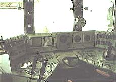
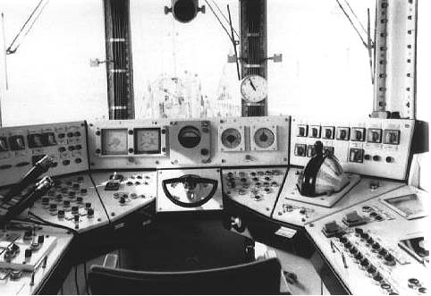
8. NAVIGATION EQUIPMENT / SHIP'S COMMAND SYSTEM.
Gyro compass installation 'GAZELLE 2'.Manufacturer: Poland
Air-cooled, meridian searching gyrocompass installation with self over-watching, for determination of the NORTH-direction of the meridians.The determinated straight directioned course of the ship is transferred to secondary equipment and displayed and stored into special systems.
Essential technical data:
- Preparation time: - Without preheating and without synchronisation : 6 Hours.
- With preheating and synchronisation : 1 Hour.
- Using time: - Continuous use.
- Using stages: - Preheating : System is heated, without gyro use.
- In use : System is not heated, gyro is in use.
Indication tolerance:- The mother-equipment with non-moving ship : +- 0,2 /
- The secondary-equipment at constant course and constant speed: +- 1,0 /
- Geographical application area: up to 80 / North or South-latitude.
Working temperature of the bearing-liquid: 50 /C +- 2 k.
Energy provision: - Board net: 380 Volt; 50 Hz.
24 V DC for the signal system.
- Transformer, secondary: 3 x 100 Volt; 400 Hz.
- Magnetic compass posture ARKONA. Manufacturer: GERMANY
Magnetic compass with reflexion optics for course indication at the wheel house on the bridge.
Essential technical data:
- Gas tight, heatable light-shaft.
- Reading accuracy of the course: 0,5 /
- Energy provision of the lighting : - Board net: 220 Volt; 50 Hz.- 24 Volt DC.
The use of the magnetic compass anticipates the execution of a compensation and indication of the rest-deviation.-Electrical compensation system EK-III-L. Manufacturer:GERMANY
Three-components compensation system to compensate the magnetic disturbance at the site of the magnetic compass, which is caused by the use of the in the ship installed three-component MES system.
The compensation is done in this way that, (by the EK-system, which can be manual adjusted), with help of the in the compass-platform installed air core coil, a magnetic field is produced which counteracts the magnetic disturbance by opposite polarity.
Essential technical data:
- Preparation time:- Non, starts immediate when MES-system is switched on.
- Using time: - Continuous use.
- Energy provision: - Through MES-system 220 Volt, A.C. max. 50 Watt.
- Through ships' system 110 Volt, 50 Hz. max. 60 VA.
- Manual steering device HSA IV.
Through the manual steering device and the by this steered electro-hydraulic stirring apparatus, the ship is kept at accurate course.
An information display shows the stirrer's position.
The electro-hydraulic stirring apparatus works with regulating pumps.
Essential technical data:- Preparation time: - Time to start the complete stirring apparatus only.
- Using time: - Continuous use.
- Required time to engage stirring device :max. 28 sec from hard-point to hard-point.
- Hard-point : 35 degrees Starboard., 35 degrees Port .
- Energy provision: 110 Volt, 50 Hz. 80 VA.
-Echo sounder system SP-4301. Manufacturer: Poland
The system measures the water depth under the keel and registers the same at a plotter as echo gram
Essential technical data:- Preparation time: - Non, starts immediate when switched on.
- Measuring ranges:
-Main measuring range I 0 - 60 m
II 0 - 100 m
III 0 - 600 m
-Partial measuring range I 50 - 110 m
II 150 - 330 m
III 500 - 1100 m
- Smallest measurable water depth: 1 m
- Indication-accuracy: +- 3 % of the measured depth.
- Frequency of the transmit/receive swingler: 31 kHz
- Energy provision: 220 Volt, 50 Hz; 70 VA
-Moving measuring system 4601. Manufacturer: Poland
Electrodynamic moving-measurement system to measure the component's X and Y of the ship's displacement through the water, as well as the sailed distance/way.
The indicated values are digitally displayed.
Essential technical data:
- Preparation time: max. 20 minutes.
- Measuring ranges: - V x ahead 0 - 39,9 sm/Hr.reverse 0 - 15,0 sm/Hr.- V y to starboard
or to port 0 - 9,9 sm/Hr.- Distance: 0 - 9999,9 sm
- Indication accuracy: Speed: 0,3 sm/Hr.Distance: 2 %
- Energy provision: 220 Volt, 50 Hz; 100 VA
- Direction finding / measuring system ARC-1404. Manufacturer: Poland.
Automatic radio position measuring system for position-determination of the ship according to radio stand-lines, as well as for the radio-guidance in case of a radio-fire or a damaged ship.The set frequency and the indicated measuring are digitally displayed.The use of the direction finder anticipates/requires a radio-signal broadcast and determination of the rest-deviation.
Essential technical data:
- Preparation time: max. 2 minutes.
- Time to check the use/capability and internal checkup: 20 minutes.
- Using time: momentary use.
- Sort of use: - Receiving- Adjusting - Relative positioning - Direct pointing positioning
- Frequency ranges: - Range I 250 - 550 kHz - Range II 1600 - 3000 kHz
- Receiving sorts of transmissions: AO, A1A, A2A, H2A, A3E, H3E - Accuracy: +- 1 /- Accuracy of the frequency indication: - Range I 100 kHz - Range II 1 kHz
- Energy provision: 220 Volt, 50 Hz; 30 VA
-Radio navigation receiver 'PIRS 2'.Manufacturer: U.S.S.R.
This system is the latest development of the 'PIRS 1' radio navigation receiver. It is used for the search/determination of the place/line values of the DECCA-navigation system,which are used in the special nautical charts, giving the location of the ship.The indication of the hyperbolic values is digitally in the PIRS 2.
Essential technical data:- Preparation time: 30 minutes.- Synchronisation time: 2 minutes.
- Using time: Continuous use.- Sort of use: - Warming-up.- Adjustment.- Operation.
- Energy provision: 220 Volt, 50 Hz; 30 VA
9. PROTECTION SYSTEMS AND -MEASURES.
9.1 N.B.C.-protection.The ship is foreseen with a nuclear-radiation measuring system with a measuring probe.For protection against mass-destruction means, the living quarters, mess room, kitchen, sanitary installations, electrical workshop, and wheel house form an hermetically closed block. An EEE-section is installed in the deck house. It exists of the combined lock- ,undressing and KC-control room, shower room and the dressing and KC-control room.
There is no hermetically closure of the engine room, here is only the ventilation prepared for the use of the large FS 2000 filter.
The ship has a water-protection (spraying) system and is foreseen of 2 SEES-systems.
9.2 SMOKE -System.
4 units of smoke-barrels in supports at the bulwark of the after body.
9.3 MAGNETIC-Protection. MES-system installed.
9.4 ACOUSTIC-Protection. Elastic support of all equipment which has rotating and oscillating mass.
10. STORES.
- Diesel oil DK-1 23 m;
- Lubrication/engine oil MD-402 0,70 m;
- Cooling water 0,80 m;
- Provisions for 8 days.
11. CREW. The ship can be used (naval service) with single (7 men) or double shift (12 men).
The standard crew exists of following 7 persons :
- 1 Captain.
- 1 First technical officer/mechanical engineer.
- 1 Helmsman.
- 1 Boatswain.
- 1 Cook.
- 1 Assistant mechanical engineer.
- 1 Deck-crew.
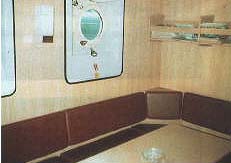
The captain and the first officer are accommodated in single rooms in the deckhouse, the rest of the crew in twin rooms under the deck. All rooms are foreseen of reserve bets for eventual double use.


IThis is an extremely well-balanced ship, having 80 percent less vibrations than building class requested !
*Please note that this are the technical MINIMUM data, all the TEST-DATA that we just got from the NAVY surpass all these building requirements. (By example turning in 1, 1 ship's length instead of 1,7 etc.).
The combination of engine, gearbox and sophisticated pitch-propeller system proofed it self to be able to handle the large landing crafts (Type 109) etc. in combination with the steering system, in the test-report, all with great-ease and extreme high manoeuvrability.
A complete TEST-REPORT of the '414'-tug is also available (+-265 pages); showing that the ship surpassed all building requirements set by the Navy!
We can provide you with a copy at inspection.All plans and technical documents are also on board. Both the original builders as well as sub-suppliers can provide any & all service required.All major equipment is from GERMAN origin, and producers confirmed availability of spares etc.
The evaluations of two shipyards, estimating building cost of this tug now at 5.6 / 7.0 mil US$
SOLD